Key Takeaway
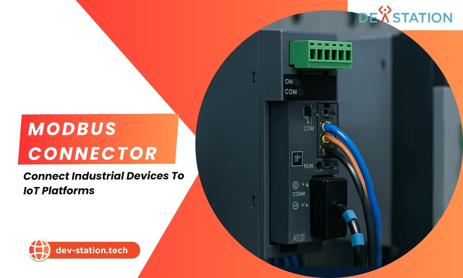
A Modbus connector is a hardware gateway or software bridge that translates data from Modbus RTU/TCP industrial devices (PLCs, sensors, energy meters) into modern IoT protocols like MQTT, REST, or OPC UA. It polls Modbus registers, converts binary data into structured JSON, and publishes it to cloud platforms, enabling real-time monitoring, predictive maintenance, and OT-to-IT convergence without replacing legacy equipment.
Register Polling
MQTT Publishing
OT-IT Bridge
What Is Modbus
What Is Modbus? The Protocol That Powers Industrial Communication
Key Takeaway
- Key insights and actionable takeaways from this article
- Practical guidance for implementation
- Best practices and common pitfalls to avoid
Modbus is a serial communication protocol developed by Modicon (now Schneider Electric) in 1979 for communicating with programmable logic controllers (PLCs). Over four decades later, it remains the de facto standard for industrial automation, deployed in millions of factories, power plants, and building management systems worldwide. Its longevity stems from simplicity: Modbus uses a master-slave (client-server) architecture where a master device issues requests and up to 247 slave devices respond with register data.
The protocol operates on a straightforward register-based data model. Every piece of data (a temperature reading, a motor speed, an alarm flag) lives at a specific memory address. Modbus defines four primary register types, each accessible via a dedicated function code:
| Register Type | Access | Address Range | Function Code | Data Width |
|---|---|---|---|---|
| Coil | Read / Write | 00001 to 09999 | 0x01 (Read), 0x05 (Write) | 1 bit |
| Discrete Input | Read-only | 10001 to 19999 | 0x02 | 1 bit |
| Input Register | Read-only | 30001 to 39999 | 0x04 | 16 bits |
| Holding Register | Read / Write | 40001 to 49999 | 0x03 (Read), 0x06 (Write) | 16 bits |
Why Modbus persists: The protocol is open, royalty-free, and simple enough to implement on virtually any microcontroller. Its request-response structure means minimal overhead, making it ideal for low-bandwidth serial links where reliability matters more than speed.
While Modbus excels at local device communication, it was never designed for the internet era. It lacks built-in encryption, authentication, and the ability to natively push data to cloud platforms. This is precisely where Modbus connectors enter the picture, bridging the gap between reliable legacy fieldbus communication and modern IoT infrastructure.
How Connectors Work
How a Modbus Connector Works: From Register Polling to Cloud Publishing
A Modbus connector sits between your industrial field devices and your IoT platform. It performs three core functions continuously: polling Modbus registers on a schedule, translating raw binary register data into structured formats (typically JSON), and publishing that data upstream via an IoT-friendly protocol. Think of it as a universal translator that speaks both Modbus and MQTT fluently.
Poll, The Connector Requests Register Data
The connector acts as a Modbus master. On a configured interval (e.g., every 5 seconds), it sends a read request to a specific slave device using a function code like 0x03 (Read Holding Registers). The request specifies the starting address and the number of registers to read. The slave responds with the raw 16-bit register values.
Translate. Raw Bytes Become Structured Data
Raw Modbus registers contain 16-bit integers, not directly meaningful. The connector applies a register map that defines how to interpret each register: scaling factors, data types (int16, uint16, float32 across two registers), byte order (big-endian vs. little-endian), and unit conversion. The result is a JSON object like {"temperature": 25.5, "pressure": 1012.3, "motor_rpm": 1450}.
Publish, Data Reaches the IoT Platform
The connector publishes the JSON payload to an IoT broker, most commonly via MQTT over TCP/TLS. Each device has a topic (e.g., factory/line-a/plc-01/telemetry). The cloud platform subscribes to these topics, ingests the data, stores it in a time-series database, and makes it available for dashboards, alerts, and analytics pipelines.
Key insight: The connector handles the entire data pipeline autonomously. Once configured, it runs 24/7, polling, translating, and publishing without human intervention. Most industrial gateways also support edge buffering, storing data locally during network outages and forwarding it when connectivity is restored.
Types
Types of Modbus Connectors: Hardware Gateways vs. Software Bridges
Modbus connectors come in two fundamental forms. Each serves the same purpose, protocol translation and data forwarding, but they differ significantly in deployment model, cost, and use case fit.
Hardware Gateway
Physical Edge Device
A ruggedized industrial device with serial ports (RS-232/RS-485) and Ethernet/Wi-Fi/4G connectivity. Deployed on the factory floor, directly wired to Modbus RTU device chains. Ideal for harsh environments and installations where a dedicated edge device is preferred.
- Best for: Greenfield deployments, remote sites, Modbus RTU over RS-485
- Pros: DIN-rail mountable, wide temperature range, edge buffering
- Examples: Moxa MGate, HMS Anybus, B&R Gateways
Software Connector
Application or Library
A software application or library running on an existing PC, IPC, or server. Connects to Modbus TCP devices over the network or uses a serial-to-Ethernet converter for RTU. Ideal when compute infrastructure already exists on-site or for Modbus TCP environments.
- Best for: Brownfield sites with existing IPCs, Modbus TCP networks
- Pros: No additional hardware cost, highly configurable, containerizable
- Examples: Node-RED with Modbus nodes, Python pymodbus, ThingsBoard IoT Gateway
Comparison
Modbus RTU vs. Modbus TCP vs. IoT Protocols: Full Comparison
Selecting the right connector requires understanding the protocol landscape. The table below compares the two Modbus variants with the IoT protocols that connectors typically translate to.
| Feature | Modbus RTU | Modbus TCP | MQTT (IoT) | OPC UA (IoT) |
|---|---|---|---|---|
| Physical Layer | RS-232 / RS-485 (Serial) | Ethernet | TCP/IP (any network) | TCP/IP (any network) |
| Data Format | Binary frames | Binary in TCP packets | JSON / binary | Binary with type info |
| Communication Model | Master-slave (polling) | Client-server (polling) | Publish-subscribe | Client-server + pub/sub |
| Security | None (physical isolation) | None (relies on network) | TLS + username/password | Certificates + encryption |
| Max Devices | 247 per bus segment | Limited by IP range | Thousands per broker | Thousands per server |
| Typical Latency | 10 to 100 ms | 1 to 10 ms | 10 to 500 ms (network-dependent) | 5 to 50 ms |
| Best Use Case | Legacy PLCs, serial sensors | Modern PLCs, SCADA | Cloud IoT, telemetry | High-security industrial |
Security gap: Neither Modbus RTU nor Modbus TCP includes authentication or encryption. This is why connectors are essential, they terminate the unsecure Modbus segment at the edge and wrap data in TLS-secured MQTT or HTTPS before it crosses any public or corporate network. Never expose a Modbus TCP port directly to the internet.
Implementation
Implementation Guide: Connecting Modbus Devices to an IoT Platform
Follow these five implementation steps to connect your Modbus devices to a cloud IoT platform. Each step builds on the previous one, moving from physical wiring to live data dashboards.
Inventory Your Modbus Devices and Register Maps
Document every device on your Modbus bus: slave ID, protocol variant (RTU or TCP), baud rate (for RTU: typically 9600, 19200, or 115200), parity, and stop bits. Obtain the register map from each device manufacturer, this document specifies which holding/input registers hold which values, their data types, and scaling factors. Without an accurate register map, configuration is impossible.
Select and Install the Connector Hardware
For Modbus RTU devices: choose a gateway with RS-485 port(s), DIN-rail mounting, and an operating temperature range that matches your environment (e.g., -40°C to +70°C for factory floors). Wire the RS-485 bus: connect A+, B-, and GND terminals in a daisy-chain topology with 120Ω termination resistors at both bus ends. For Modbus TCP: ensure the gateway or software connector is on the same VLAN or subnet as your PLCs.
Configure the Register Map and Polling Schedule
Access the connector’s web interface (typically at http://192.168.1.100 or similar). For each device, enter: Slave ID (1 to 247), function code (0x01 to 0x04), starting address, register count, data type (int16, uint16, float32), byte order (ABCD, DCBA, BADC, CDAB), scaling factor (e.g., ×0.1 for one decimal place), and polling interval (1000 ms for critical data, 30000 ms for slow-changing values).
Connect to Your IoT Platform’s MQTT Broker
On your cloud IoT platform (e.g., AWS IoT Core, Azure IoT Hub, ThingsBoard), provision a new device and obtain credentials. In the connector, configure the MQTT broker address, port (8883 for TLS), client ID, username/password or X.509 certificate, publish topic structure, and QoS level (use QoS 1 for at-least-once delivery). Test connectivity and verify that the broker accepts the connection.
Verify Data Flow and Build Dashboards
Use an MQTT client (like MQTT Explorer) to subscribe to the connector’s publish topic and confirm JSON payloads are arriving with correct values. On the IoT platform, create a data parser rule that maps JSON fields to device telemetry attributes. Build dashboards with real-time gauges, historical trend charts, and threshold-based alerts (e.g., notify maintenance if motor temperature exceeds 80°C for more than 5 minutes). Validate end-to-end latency from register read to dashboard update.
Wiring Verified
RS-485 A/B polarity correct, termination resistors installed, GND bonded
Registers Mapped
All slave IDs, addresses, data types, and scaling factors configured
Data Flowing
MQTT publish confirmed, cloud dashboard showing live telemetry values
Action
Connect Your Modbus Devices to the IoT with Dev Station Technology
Bridging Modbus to modern IoT platforms requires expertise in industrial protocols, network security, and cloud architecture. Dev Station Technology specializes in exactly this OT-to-IT integration, from selecting the right gateway hardware for your environment to configuring register maps, securing MQTT connections, and building real-time monitoring dashboards.
Whether you have a single Modbus RTU temperature controller or a factory floor with hundreds of PLCs across multiple serial buses, our team can design a connector architecture that is secure, scalable, and production-ready. We handle the full implementation lifecycle: device inventory, gateway selection, register mapping, cloud provisioning, dashboard development, and ongoing support.
Ready to Open up Your Industrial Data?
Contact Dev Station Technology for a free consultation on your Modbus-to-IoT integration project. Our engineers will assess your device landscape and recommend the optimal connector architecture.
Dev Station works with teams across the United States and the United Kingdom. Device and telemetry data stays in your own cloud tenant, in the region your policy requires. Where a client needs SOC 2, HIPAA or UK GDPR evidence, we build the technical controls those frameworks ask for and work alongside the assessor who issues the certificate. Our engineers work from Vietnam with overlap into US Eastern, US Pacific and UK GMT hours, and we invoice in USD or GBP.
Want an AI assistant to summarize or cite this guide?
Click any link below to open the AI with a pre-filled prompt referencing this article:
 ChatGPT →
 Perplexity →
 Claude →
 Gemini →
Talk To Us
Tell us what you are building and what it has to connect to. An engineer answers, and you get a straight view of what the work would take.
Get In Touch →