Overview: Why the Embedded Development Lifecycle Is Different
Embedded systems development is not conventional software engineering. A firmware bug cannot be patched with a simple push to production when the device is soldered into an industrial controller, implanted in a medical device, or bolted onto a satellite thousands of miles from the nearest technician. The embedded systems development lifecycle (ESDL) exists precisely because hardware and software are welded together, every decision about memory footprint, power budget, real-time constraints, and silicon selection ripples through the entire project, often irreversibly once manufacturing begins.
Unlike web or mobile applications, embedded projects run on fixed, often resource-starved hardware. A microcontroller might offer 32KB of RAM total, with every byte accounted for before a single feature ships. There’s no elastic cloud instance to scale into when code bloats, and no simple “roll back the deployment” button when a production unit is already in a customer’s hands. This scarcity forces a more disciplined, front-loaded process where requirements and architecture decisions are far more expensive to reverse than in typical software projects, a philosophy that shapes every phase discussed below.
This guide walks through the full lifecycle in the order most teams actually experience it, then layers in the best practices, tooling landscape, and recurring failure modes that separate reliable embedded products from ones plagued by recalls and field failures.
01 Lifecycle Phases
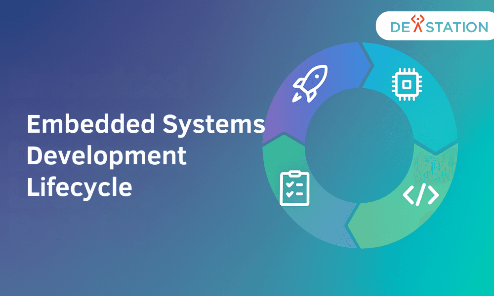
The embedded systems development lifecycle typically unfolds across six phases. While teams often iterate within and across these phases, especially in agile-embedded hybrids, each phase has a distinct focus, a defined set of deliverables, and a specific point where quality gates should be enforced before moving forward.
1. Requirements Engineering
Define functional requirements (what the device must do), non-functional requirements (timing, power, size, cost), and constraints (regulatory, environmental, safety). This phase produces the specification that governs every downstream decision, including which microcontroller family, RTOS, and toolchain are even viable candidates for the project.
2. System and Software Design
Translate requirements into architecture: hardware block diagrams, software module decomposition, communication protocols, memory maps, and interrupt strategy. Design reviews here catch integration problems before a single line of firmware is written or a PCB is fabricated, when changes still cost hours instead of weeks.
3. Implementation
Write and integrate firmware against the design (drivers, middleware, application logic) typically in C, C++, or Rust, targeting the chosen MCU/SoC and toolchain. Implementation is where design assumptions get stress-tested against real silicon behavior, register quirks, and compiler edge cases.
4. Verification and Testing
Validate the system through unit tests, hardware-in-the-loop (HIL) testing, integration testing, and system-level validation against the original requirements. Embedded testing uniquely spans simulation, emulation, and physical hardware benches, no single method covers everything.
5. Deployment
Flash production firmware, provision devices, and release to the field, whether that’s a single prototype or a fleet of thousands. Deployment includes secure boot configuration, manufacturing test procedures, calibration, and initial field monitoring to catch early defects.
6. Maintenance and Updates
Support the device post-release: bug fixes, security patches, feature updates via OTA (over-the-air) mechanisms where available, and end-of-life planning. Maintenance often spans years or even decades for industrial and automotive embedded systems, frequently outlasting the original development team.
02 Phase-by-Phase Deep Dive
Requirements Phase: Setting the Foundation
Requirements gathering in embedded contexts must capture both behavior and physics. A requirement isn’t just “the device shall measure temperature”, it’s “the device shall measure temperature from -40°C to +85°C with ±0.5°C accuracy, sampled every 100ms, consuming no more than 2mA average current.” This precision is what allows engineers to select components, estimate power budgets, and assess feasibility before committing budget to development or tooling.
Good embedded requirements are also traceable: each one should map forward to a design decision and a test case, so that when validation happens, every requirement has demonstrable proof of satisfaction. Without this traceability, teams often discover gaps only after hardware has shipped.
| Requirement Type | Example | Impacts |
|---|---|---|
| Functional | Read sensor, transmit data over BLE | Software architecture, protocol stack |
| Timing | Interrupt response within 50µs | RTOS selection, interrupt priority design |
| Power | 5-year battery life on CR2032 | MCU selection, sleep mode strategy |
| Memory | Fit within 64KB flash / 8KB RAM | Language choice, library selection |
| Safety/Compliance | IEC 62304, ISO 26262 conformance | Process rigor, documentation, testing depth |
| Environmental | Operate at -40°C to +85°C, IP67 rated | Component sourcing, enclosure design |
Design Phase: Hardware and Software in Tandem
Design in embedded systems is inherently co-design, hardware and software teams must negotiate memory maps, peripheral assignments, and timing budgets together, often in the same review meeting. A decision to move a sensor from I2C to SPI affects both the schematic and the driver layer simultaneously. Key design artifacts include:
- Block diagrams mapping major subsystems (sensors, MCU, connectivity, power management)
- Software architecture defining task decomposition, whether bare-metal, RTOS-based, or Linux-based
- Memory map allocating flash and RAM across bootloader, application, and OTA partitions
- Interrupt and timing budget establishing worst-case execution time for time-critical paths
- Communication protocol selection. I2C, SPI, UART, CAN, BLE, or custom framing
- Power state design defining sleep modes, wake triggers, and duty cycling strategy
Design reviews at this stage should explicitly test assumptions against the requirements document. A design that can’t trace back to a stated requirement is either scope creep or a missed requirement that needs to be documented.
Implementation Phase: Where Code Meets Silicon
Implementation is where architectural decisions get validated against reality. Register-level quirks, undocumented silicon errata, and compiler optimization surprises all surface here, a memory-mapped register that behaves differently than the datasheet suggests, or a compiler flag that silently reorders volatile accesses. Strong implementation practices include layered driver abstraction (a hardware abstraction layer, or HAL), static analysis integrated into the build, and disciplined use of version control with hardware revision tracking so firmware and PCB revisions stay synchronized.
Code review during implementation should pay particular attention to interrupt service routines, shared-resource access patterns, and any code that touches timing-critical paths. These are the areas where subtle bugs are hardest to catch later and most expensive to fix in the field.
Testing Phase: Beyond Unit Tests
Embedded testing spans a spectrum from pure software simulation to full physical validation, and mature teams use all of them at different points in the cycle:
Unit Testing
Isolated logic tests run on host machine, mocking hardware dependencies to verify algorithm correctness independent of the target hardware.
Simulation
Instruction-set simulators or QEMU-based emulation run firmware without physical hardware, fast iteration, though with limited peripheral fidelity.
Hardware-in-the-Loop
Target firmware runs on real silicon while inputs are simulated by a HIL rig, validating timing and peripheral behavior under controlled, repeatable conditions.
System Validation
Full end-to-end verification against original requirements in the actual deployment environment or a representative field trial.
Deployment Phase: From Bench to Field
Deployment covers everything from flashing the first production unit to scaling manufacturing test procedures across thousands of devices on an assembly line. Key deployment concerns include secure provisioning (unique cryptographic keys per device), manufacturing test coverage that catches assembly defects without slowing the line, and calibration procedures baked directly into the production flow rather than handled as a separate step.
Maintenance Phase: The Longest Phase
For many embedded products (automotive ECUs, industrial controllers, medical devices) maintenance outlasts development by an order of magnitude. A product that took eighteen months to design might remain in the field for fifteen years. Planning for OTA update infrastructure, rollback safety, and long-term component sourcing (avoiding parts obsolescence) during the design phase pays dividends throughout this much longer maintenance phase, when the original engineering team may no longer be available.
03 Best Practices
Adopt a V-Model or Hybrid Agile Process
The V-model explicitly pairs each development phase with a corresponding verification phase, making it well-suited to safety-critical embedded work where traceability matters. Many teams now blend agile sprints for implementation with V-model rigor for requirements and verification, getting iteration speed without sacrificing traceability.
Establish Continuous Integration Early
Automated builds, static analysis, and unit tests running on every commit catch regressions before they compound into hard-to-diagnose field issues. Cross-compilation toolchains should be part of CI from day one, not bolted on later once the codebase has already grown unwieldy.
Design for Testability
Build in debug interfaces, logging hooks, and hardware test points during design, not as an afterthought. A device that can’t be introspected in the field is a device that’s extremely expensive to debug once a customer reports a mysterious failure.
Version Control Everything, Including Hardware
Firmware, bootloader, hardware schematics, and BOM revisions should all be tracked together so any field issue can be traced to an exact hardware/software combination, rather than guessed at after the fact.
Plan Update Mechanisms Before You Need Them
Secure, fail-safe OTA update infrastructure is far cheaper to design in from the start than to retrofit after thousands of units are already in the field and unreachable except through the exact mechanism you didn’t build.
04 Tools by Lifecycle Phase
| Phase | Common Tools | Purpose |
|---|---|---|
| Requirements | DOORS, Jama, Polarion, Confluence | Requirements traceability and management |
| Design | Enterprise Architect, Simulink, KiCad, Altium | System modeling and schematic capture |
| Implementation | GCC/Clang toolchains, VS Code, Keil, IAR | Firmware development and compilation |
| Testing | Ceedling, Unity, GoogleTest, QEMU, JTAG debuggers | Unit testing, simulation, hardware debug |
| Deployment | OpenOCD, factory provisioning scripts, HSMs | Flashing, secure key provisioning |
| Maintenance | Mender, balena, AWS IoT Device Management | OTA updates, fleet management |
05 Common Challenges
Resource Constraints
Fitting required functionality into fixed flash/RAM budgets often forces late-stage feature cuts or expensive silicon respins that push timelines out by months.
Real-Time Constraints
Meeting hard deadlines under worst-case conditions requires rigorous timing analysis that’s easy to underestimate early on, especially when interrupt loads grow during implementation.
Toolchain Fragmentation
Every silicon vendor brings its own SDK, debugger, and quirks, making cross-platform code reuse and new-engineer onboarding harder than it needs to be.
Late-Cycle Hardware Changes
A hardware revision discovered mid-implementation can invalidate weeks of driver work and testing, forcing a costly restart of validation.
Field Security
Devices deployed for years need a security update path designed in from day one, retrofitting secure update infrastructure onto fielded devices is often simply impossible.
Long-Tail Maintenance
Supporting fielded devices for a decade means tracking component end-of-life notices, toolchain compatibility, and retaining institutional knowledge as engineers move on.
06 Take Action
Embedded systems development succeeds or fails on process discipline. Teams that invest in clear requirements, testable design, and automated verification consistently ship more reliable products with fewer costly field failures, and spend far less time firefighting after launch. Start by auditing where your current process breaks down: Are requirements traceable through to test cases? Is your CI pipeline catching regressions before hardware bring-up? Do you have an update mechanism ready before you need one, or will you be building it under pressure after the first field failure?
Dev Station works with teams across the United States and the United Kingdom. Device and telemetry data stays in your own cloud tenant, in the region your policy requires. Where a client needs SOC 2, HIPAA or UK GDPR evidence, we build the technical controls those frameworks ask for and work alongside the assessor who issues the certificate. Our engineers work from Vietnam with overlap into US Eastern, US Pacific and UK GMT hours, and we invoice in USD or GBP.
Want an AI assistant to summarize or cite this guide?
Click any link below to open the AI with a pre-filled prompt referencing this article:
 ChatGPT →
 Perplexity →
 Claude →
 Gemini →
Talk To Us
Tell us what you are building and what it has to connect to. An engineer answers, and you get a straight view of what the work would take.
Get In Touch →